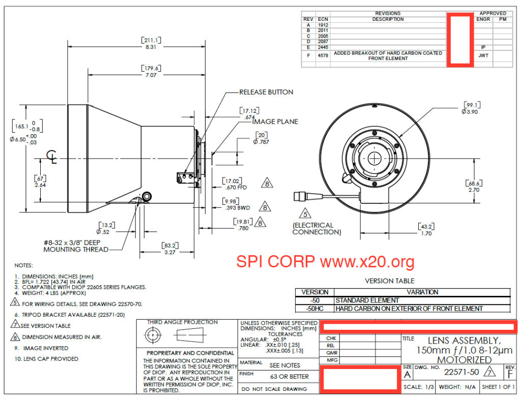
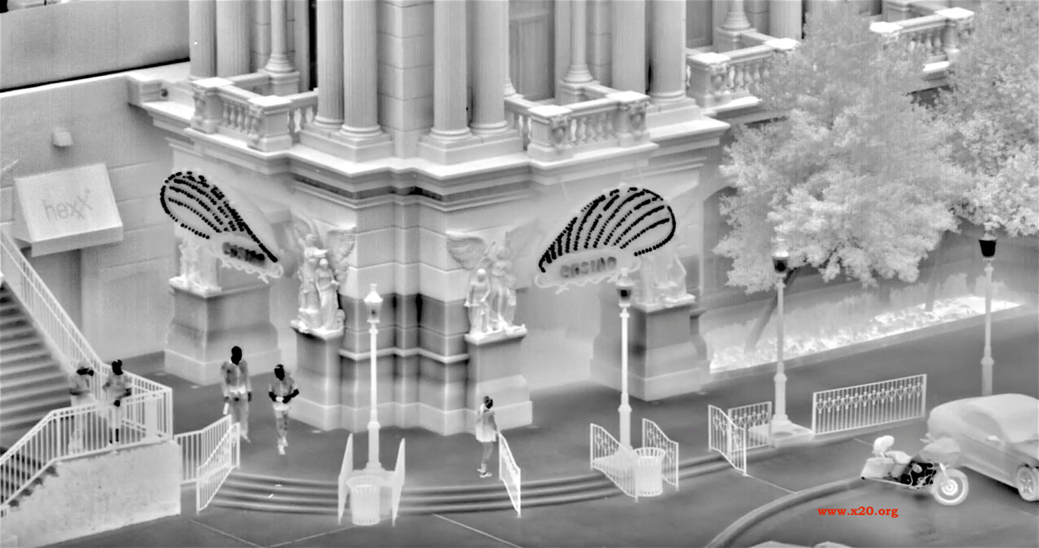
Long Range MWIR and LWIR uncooled long wave cooled mid wave thermal infrared security cameras with continuous zoom Germanium Lenses
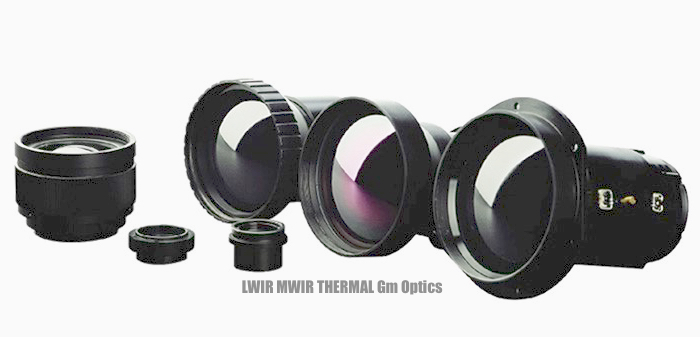

LWIR uncooled and MWIR cooled zoom thermal imaging Flir ir germanium optical lenses by SPI
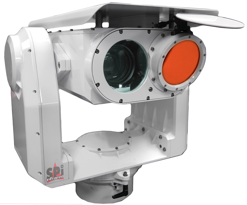
When you need the advantages of full stabilized long range pan tilt zoom (PTZ) flir (Forward Looking InfraRed) thermal imaging cameras, SPI Corp can custom design/engineer the perfect Dual sensor & Multi Sensor PTZ (Pan Tilt Zoom) FLIR thermal imaging system for you. If you require custom special design and integration at affordable pricing, SPI will cater to your mission requirements.
CLICK ON A LONG RANGE THERMAL CAMERA SELECTION BELOW;
M7 LWIR PTZ LONG RANGE THERMAL CAMERA
M9 MWIR LONG RANGE FLIR THERMAL CAMERA

M11 MWIR FLIR PTZ LONG RANGE THERMAL CAMERA

M1D LONG FIXED VEHICLE FLIR PTZ LONG RANGE THERMAL CAMERA
M2D LONG RANGE EO/IR DRONE GIMBAL THERMAL CAMERA

M5 PTZ LONG RANGE THERMAL CAMERA

SPI long range cooled MWIR thermal camera with laser range finder-SPI
CLICK ON THE IMAGE ABOVE TO SEE VIDEO EXAMPLES
of the M9 COOLED LONG RANGE
The low cost, affordable defender series of MWIR 3-5 um micron thermal imaging flir infrared cameras are rugged, waterproof, very high performance, high sensitivity, ultra long range rugged all weather cameras. These systems can be used as standalone camera or integrated into imaging systems. The units provide 24/7 security and surveillance imagery in the most demanding environments.
SPI UTILIZES THE HIGHEST QUALITY CURRENT TOP GRADE MILITARY PTZ FLIR THERMAL IMAGING CAMERA SENSORS WHICH OFFER THE HIGHEST SENSITIVITY AND GREATEST IMAGE DETAIL WHICH RESULTS IN BETTER DETECTION, RECOGNITION & IDENTIFICATION OF LONG RANGE TARGETS
SPI offers a robust selection of Multiple Heavy Duty Long Range Pan Tilt Zoom PTZ FLIR thermal imaging cameras for HD Day and night vision surveillance imaging in military, border, shoreline and coastal security applications. Our All Weather IP68+ Platforms are submersible & offer the best reliability and performance of any long range FLIR thermal imaging system available anywhere.
The defender series comes with your choice of a multitude of different thermal ir lenses to achieve multi kilometer long range detection ranges
Highly precise optical mechanism provide smooth, clean continuous zoom lenses coupled with military grade MWIR 3-5 Um detectors engines. The defender series of cameras come in a wide selection of long range lens choices. These cameras are easy to integrate and very simple to use. The defender thermal imaging cameras provide healthy detection ranges from 5 kilometers up to 60 kilometers.

LENS OPTIONS:
15-225 mm MWIR continuous zoom hardened, coated/sealed germanium lens.
18-335 mm MWIR continuous zoom hardened, coated/sealed germanium lens.
35-670 mm MWIR continuous zoom hardened, coated/sealed germanium lens.
35-720 mm MWIR continuous zoom hardened, coated/sealed germanium lens.
35-835 mm MWIR continuous zoom hardened, coated/sealed germanium lens.
88-1420 mm MWIR continuous zoom hardened, coated/sealed germanium lens.
15-305 mm MWIR continuous zoom hardened, coated/sealed germanium lens.
47-595 mm MWIR continuous zoom hardened, coated/sealed germanium lens.
88-1220 mm MWIR continuous zoom hardened, coated/sealed germanium lens.
55-1650 mm MWIR continuous zoom hardened, coated/sealed germanium lens.
Custom WFOV to Ultra Extreme NFOV Long Range cooled thermal MWIR mid wave lenses are available.
Contact mike@x20.org for additional info or call 702-499-9551
Please select HD mode while viewing the videos below on youtube to get the best viewing experience and proper frame rate.
SPI’s Defender long range Cooled MWIR (3000 nanometers to 5000 nanometers) Thermal infrared imaging cameras enables users to see sharp details at ultra long range without depleting situational awareness with high fidelity image enhancement features. The Units Sharp continuous zoom Germanium lenses allow for exact telephoto zooming throughout the entire zoom cycle without having to re focus and re adjust image NUC. The Defender is a fully auto imaging system which allows the user perfect image detail at all time in all environments.
MX6 THE WORLDS MOST AFFORDABLE LONG RANGE STABILIZED PTZ COOLED MWIR THERMAL IMAGING CAMERA WITH ZOOM TV CAMERAS AND LASER RANGE FINDER
CLICK HERE FOR THE WORLDS LOWEST COST MX6 FLIR PTZ thermal imaging long range multi sensor pan tilt MWIR camera system

M7 EOIR PDF PTZ FLIR LONG RANGE THERMAL IMAGING SYSTEM BROCHURE

Using an extremely reliable closed cycle cooled MWIR INSB or HOT MCT detectors, the Defender Long range imager provides exceptional long range performance with detection of human targets beyond 30 kilometers and vehicles beyond 40km with specialty F4 optics. The systems also have smooth continuous zoom to maintain situational awareness with target focus in both a wide field of view (Wfov) and narrow field of view (Nfov). This capability ensures users always have an optimized Wfov and Nfov for targets at any range.
The system also features Image Contrast/Detail sharpening algorithms developed to generate an optimal image with minimal adjustment. Select units have image stabilization integrated in the camera for jitter and shake free viewing.
 CLICK HERE FOR THE NEW EXOTIC ULTRA LONG RANGE MULTI
SENSOR STABILIZED M11 PTZ FLIR THERMAL SURVEILLANCE IMAGING SYSTEM
The Defender Long Range thermal FLIR imaging cameras are designed to work 24/7 with unmatched reliability for ISR, C4ISR, and RSTA, security, surveillance, border, radar and coastal EOIR applications.
SPI’s Defender Series Cooled MWIR INSB Indium Antimonide are highly sensitive cameras, which can detect the slightest temperature difference between cameras. They can be designed to enable imaging in the mid-wave infrared (MWIR) band of the spectrum, where there is a high thermal contrast because of blackbody physics. Thermal contrast can be termed as a signal change for a target temperature change. The more thermal contrast there is, the easier it is to determine objects against a background not hotter or colder than the object. Cooled MWIR cameras offer exceptional capabilities in high sensitivity and are crucial for ultra extreme long range thermal imaging. LWIR mostly Amorphous silicon or microbolometer uncooled cameras have their space in long range thermal IR FLIR imaging, but only up to a certain point, they cannot achieve the Ultra Very long ranges that MWIR or HOT MCT (mercury cadmium telluride) cameras can.
SPI’s Defender MWIR camera offer you sharp, clean crisp image detail at extreme long zoom distances. Having the unique capability of Detecting Human activity at pitch dark, at
ranges in excess of 30 Kilometers offers a clear advantage in tactical situations. The farther you are away from the target, they better off you are to assess the situation and react.
Long-range surveillance in low-light conditions or total darkness is a perfect application for thermal infrared flir imaging technology. This type of surveillance is often required at borders, remote areas & large perimeters where most threats occur at night.
SPI’s defender series of thermal infrared imaging FLIR cameras are an ideal solution for low light, harsh environment tactical imaging. Our cameras produce a day like image in all conditions. Low noise, high sensitivity and high resolution are standard features of our cooled MWIR IR cameras.
The security, law enforcement and military markets are very price sensitive and competitive.
The defender camera system is a Capitol investment that will bring years of trouble free, reliable imaging. While these cameras are not inexpensive by all means, SPI strives to offer you the best value for performance anywhere in the market.
Our IR camera systems give you substantial standoff ranges and are key where high quality, sharp picture quality is required along with impressive DRI ( Detection, Recognition, and Detection ) specifications. Highly precise coated & hardened optical germanium lenses allow you to discern friend from foe at long distances. Our precision micro cryocoolers which are an integral part of a cooled thermal MWIR imaging camera are built to last for many years.

Thermal imaging flir IR Lenses
The Lens of a THermal,imaging ir camera is not made out of glass like the lens of a normal CCTV camera. The properties of glass mean that it does not transmit infrared radiation very well and would be an impractical lens material for thermal imagers. Instead Germanium is used for Flir lenses.
Germanium is a naturally occurring chemical element that is transparent to IR Radiation (that is that it will allow IR Radiation to pass through it). Although abundant on the planet, few minerals contain it in large concentrations making Germanium expensive to mine. This, combined with its semi-conductor properties and uses in communication equipment such as fibre optics mean that Germanium carries a high market value (currently 1Kg of unprocessed Germanium is Aprox $1,150, the equivalent weight in silicon is Aprox $1.50).
The high price of Germanium lenses makes it a significant factor in the cost of any Thermal infrared system. Obviously the more germanium used on the lens, the higher the price of the system. This explains why thermal imagers that can see further that 2 kilometres and can detect objects in excess of 40 km (and therefore require large lenses) are significantly more expensive than those designed to focus on less than 300 meters.
Finally there is the factor of size. Long-range thermal imagers require large lenses. These large lenses are heavy and will require significant support for stability, especially if elevated on poles or platforms. All of which contributes to the cost of a system and explains why many integrated Thermal ir imaging /CCTV Camera combinations (which often have compact housings) are designed for surveillance at Multi kilometer ranges.
Detection, Identification, Recognition D,R,I
CCTV usually uses a specific set of guidelines for Detection, Identification & Recognition (DRI) of an item or person. This typical equates to D=10%, R=50%, I=120% of screen height.
Although thermal imaging uses the same set of criteria, it was originally developed for military applications, such as surveying a battlefield, and uses the criteria in a more subjective way.
• Thermal imaging Detection: Recognition of a heat source approximately 3pixels high on-screen
• Thermal imaging Recognition: Distance at which the object can be recognised – person, animal or vehicle etc.
• Thermal imaging Identification: Originally used by the military for identification of friend or foe – typically half the Recognition range.
This difference can be misleading for security installers and integrators who are not used to Thermal imaging flir technology and can be confused by the specifications provided to them by manufacturers. For example ‘Detection’ in the CCTV world equates to an object being 10% of screen height. The equivalent on a thermal imaging camera would be 0.5% of screen height. And this is the reason why Thermal Infrared Cameras are able to ‘Detect’ at such great distances compared to conventional CCTV cameras.
Conventionally, the DRI ranges are stated as being for 50% probability of detecting a fixed target. In practice, a moving target is more easily detected by an observer. The DRI range is usually best-case and takes no account of atmospheric attenuation which can be a factor a longer ranges especially in mist or fog.
For practical CCTV type applications a reliable level of detection in a wide range of conditions will be achieved at 60-70% of the theoretical D range.
Below is a Primer on IR theory
Introduction
SWIR is also called the «reflected infrared» region since radiation coming from a light source is reflected by the object in a similar manner as in the visible range. SWIR imaging requires some sort of illumination in order to image an object and can be performed only if some light, such as ambient moon light or stars light is present. In fact the SWIR region is suitable for outdoor, night-time imaging.SWIR imaging lenses are specifically designed, optimized, and anti-reflection coated for SWIR wavelenghts. Indium Gallium Arsenide (InGaAs) sensors are the primary sensors used in SWIR, covering typical SWIR band, but can extend as low as 0.550 µm to as high as 2.5 µm.A large number of applications that are difficult or impossible to perform using visible light are possible using SWIR InGaAs based cameras: nondestructive identification of materials, their composition, coatings and other characteristics, Electronic Board Inspection, Solar cell inspection, Identifying and Sorting, Surveillance, Anti-Counterfeiting, Process Quality Control, etc… When imaging in SWIR, water vapor, fog, and certain materials such as silicon are transparent. Additionally, colors that appear almost identical in the visible may be easily differentiated using SWIR.MWIR: 3-5 μm / LWIR: 8-14 μm
MWIR and LWIR regions are also referred to as “thermal infrared” because radiation is emitted from the object itself and no external light source is needed to image the object. Two major factors determine how bright an object appears to a thermal imager: the object’s temperature and its emissivity (a physical property of materials that describes how efficiently it radiates). As an object gets hotter, it radiates more energy and appears brighter to a thermal imaging system. Atmospheric obscurants cause much less scattering in the MWIR and LWIR bands than in the SWIR band, so cameras sensitive to these longer wavelengths are highly tolerant of smoke, dust and fog.MWIR collects the light in the 3 μm to 5 μm spectral band. SPI’s MWIR cameras are employed when the primary goal is to obtain high-quality images rather than focusing on temperature measurements and mobility. The MWIR band of the spectrum is the region where the thermal contrast is higher due to blackbody physics; while in the LWIR band there is quite more radiation emitted from terrestrial objects compared to the MWIR band, the amount of radiation varies less with temperature (see Planck’s curves): this is why MWIR images generally provide better contrast than LWIR. For example, the emissive peak of hot engines and exhaust gasses occurs in the MWIR band, so these cameras are especially sensitive to vehicles and aircraft. The main detector materials in the MWIR are InSb (Indium antimonide) and HgCdTe (mercury cadmium telluride) also referred to as MCT and partially lead selenide (PbSe)
LWIR collects the light in the 8 μm to 14 μm spectral band and is the wavelength range with the most available thermal imaging cameras. In fact, according to Planck’s law, terrestrial targets emit mainly in the LWIR. LWIR systems applications include thermography/temperature control, predictive maintenance, gas leak detection, imaging of scenes which span a very wide temperature range (and require a broad dynamic range), imaging through thick smoke, etc… The two most commonly used materials for uncooled detectors in the LWIR are amorphous silicon (a-Si) and vanadium oxide (VOx), while cooled detectors in this region are mainly HgCdTe.
CLICK ON THE IMAGE ABOVE TO SEE VIDEO EXAMPLES
of the M9 COOLED LONG RANGE
MWIR EOIR PTZ IMAGING SYSTEM
The defender cooled MWIR 3-5 mid-wave EOIR / cooled LWIR 8-12 / 7-14 Microns thermal infrared cameras offer outstanding image quality in day or night and can see through environmental clutter. Low power, small form factor, high performance and weather resistant are a few key features of the defender series of cooled IR FLIR cameras. Camera systems come in a selection of INSB, MCT, HOT MCT Cooled MWIR or COOLED VGA LWIR 640 x 512 resolution or HD MWIR 1280 x 1040
An object reacts to incident radiation from its surroundings by either absorbing, reflecting or transmitting the radiation incident upon it. Therefore:α + ρ + τ = 1α = absorption coefficient 0 < α < 1
ρ = reflection coefficient 0 < ρ < 1
τ = transmission coefficient 0 < τ < 1Kirchoff’s law
At thermal equilibrium, the power radiated by an object must be equal to the power absorbedBlackbody
A blackbody is defined as a perfect radiator which absorbs and re-radiates (as stated by Kirchoff’s law) all radiation incident upon it. For a Blackbody α=1, ρ=0, τ=0Blackbody spectral radiant emittance (Planck’s Law)
The higher the temperature of an object, the higher the spectral radiant emittance (at all wavelengths) and the shorter the peak wavelength of the emissions.
Moreover emissivity is also dependent on emission angle, surface treatment and material thickness.In general, the duller and blacker a material is, the higher its emissivity. On the other hand, the more reflective a material is, the lower its emissivity. Therefore, the same material c an show extremely different emissivity values depending on the surface treatment. For example polished aluminium, which is highly reflective, has a much lower emissivity than anodized aluminium.Thermal imaging cameras calculate an object temperature by detecting and quantifying the emitted energy over the operational wavelength range of the detector. Temperature is then calculated by relating the measured energy to the temperature of a blackbody radiating an equivalent amount of energy according to Planck’s Blackbody Law. Because the emissivity of an object affects how much energy an object emits, emissivity also influences a thermal imager’s temperature calculation.Material Emissivity
Human Skin 0,98
Water 0,95
Aluminium (polished) 0,10
Aluminium (anodized) 0,65
Plastic 0,93
Ceramic 0,94
Glass 0,87
Rubber 0,90
Cloth 0,95
Tab. 1: Emissivity values of common materialsAtmospheric windows
Water vapor and gases that make up the Earth’s atmosphere tend to absorb infrared radiation coming form an object, which becomes therefore severly attenuated if radiation must be detected at great distances from the object.Thus, in order to detect the IR signal, one must use the so-called atmospheric windows (Fig. 3). Essentially two infrared atmospheric windows (bands) are available: the short/medium-wave windows spanning form 2 to 5,6 μm and the long-wave window, spanning from approximately 7,5 to 14 μm. Composition of detectors material is selected for sensitivity to one band.Types of infrared detectors
An infrared detector is simply a transducer of radiant energy, converting radiant energy in the infrared band into a measurable form. There are many detector materials with response curves that fit within the above mentioned infared windows. Infrared detectors are classified into thermal types, that have no wavelength dependece, and quantum types that are wavelenght dependent.THERMAL / NON-QUANTUM TYPESThermal IR detectors include thermocouple, thermopile, bolometer, and pyroelectric detectors. Thermal detectors, as the name suggests, change their temperature depending upon the impacting radiation. The temperature change creates a voltage change in the thermopile and a change in resistance in the bolometer, which can then be measured and related to the amount of incident radiation. Thermal detectors are much slower (response time order of ms) than quantum detectors due to the self-heating required. One of the most attractive characteristics of thermal detectors is the equal response to all wavelengths. This contributes to the stability of a system that must operate over a wide temperature range. Another significant factor is that thermal detectors do not require cooling.A microbolometer is a specific type of bolometer, i.e. a detector that measures the power of electromagnetic radiation incident upon a material which possesses the specific property of changing its electrical resistance when heated. Basically, infrared radiation strikes the detector material, heating it, and thus changing its electrical resistance, which is then measured. Microbolometers detectors are used in thermal cameras operating in the LWIR (7.5 – 14 μm) range and do not require cooling. The two most commonly used materials are amorphous silicon (a-Si) and vanadium oxide (VOx).
Advantages include: – Broad and flat response curve (wavelenght independent),- Do not require cooling,- Small and lightweight, allows compact camera designs, – Less expensive,- Low power consumption relative to cooled detector thermal imagers, – Very long MTBF (Mean Time Between Failures), while disadvantages are – Relatively low sensitivity (detectivity), – Slow response time (time constant 12 ms)QUANTUM TYPESQuantum detectors operate on the basis of an intrisic photoelectric effect and interact directly with impacting photons. These materials respond to IR radiation by absorbing photons that elevate the material’s electrons to a higher energy state, causing a change in conductivity, voltage or current.In materials used for quantum detectors, electrons are either in the conduction band, where they are free to move (and therefore conduct electrical current), or in the valence band, where they cannot move freely. When the material is cooled below a certain temperature, no electrons can be found in the conduction band and no electrical current is carried. In these conditions, when incident photons hit the material they stimulate electrons to move up into the conduction band, thus carrying a current which is proportional to the intensity of incident radiation. Since IR radiation has small energy when compared to Visibile or UV rays (energy is inversely proportional to wavelength), these detectors are cooled down to cryogenic temperatures in order to increase infrared detection efficiency/sensitivity. Cooling methods include Stirling cycle engines, liquid nitrogen and thermoelectric cooling (). Cooled thermal imaging cameras are the most sensitive type of cameras to small differences in scene temperature.
Quantum detectors react very quickly to changes in IR levels (response time order of μs), however they have response curves with detectivity that varies strongly with wavelength.
Cooled quantum detector materials include – InSb, – InGaAs, – PbS, – PbSe, – HgCdTe (MCT).Short-wave infrared (0.9 to 1.7 µm): mainly InGaAs detectors cover this region
Mid-wave infrared (3 to 5 µm): covered by Indium antimonide (InSb), HgCdTe and partially by lead selenide (PbSe)
Long-wave infrared (8 to 14 µm): this region is covered by HgCdTe and microbolometers
IR detectors performance parameters
Signal-to-noise ratio (S/N)Responsivity RResponsivity is the ability of the detector to convert the incoming radiation into an electrical signal. Responsivity measures the input–output gain of a detector system. In the specific case of a photodetector, responsivity measures the electrical output per optical input.
Noise equivalent power (NEP)
A photodetector produces some noise output with a certain average power even when it does not get any input radiation. This noise output is proportional to the square of the r.m.s. voltage or current amplitude. The noise-equivalent power (NEP) of a detector is the optical input power (P) which produces an additional output power identical to the noise power for a given bandwidth (Δf). In other words, the NEP is the light power required to obtain a signal to noise ratio S/N of 1, that is, the light level required to produce a signal current equivalent to the noise current. The units of NEP are watts per square root hertz. NEP indicates the lower limit of light detection: a smaller NEP corresponds to a more sensitive detector.
Specific detectivity D* (D-star)
D* is the photo sensitivity per unit active area of a detector. D* is conveniently used to compare the performances of various detector types since it is area-independent. D* is the signal-to-noise ratio at a particular electrical frequency, and in a 1 Hz bandwidth when 1 Watt of radiant power is incident on a 1 cm² active area detector. In other words it is equal to the reciprocal of the noise-equivalent power (NEP), normalized per unit area.
P = Incident radiant power received by the detector [W]
A = Detector active area [cm2]
Δf = Noise bandwidth [Hz]
S/N = Signal to Noise ratio
In general the measurement conditions of D* are expressed in the format of D* (X, Y, Z), where X is the temperature [K] or wavelength [μm] of a radiant source, Y is the chopping frequency [Hz], and Z is the noise bandwidth [Hz]. The units of D* are centimeter-square root-hertz per watt, sometimes referred to as “Jones” units. The higher D*, the better the detector. D* values are very high
Noise equivalente temperature difference NETD
NETD is a widely used performance parameter that characterizes the sensitivity of thermal imaging sensors. NETD is the amount of incident signal temperature that would be needed to match the internal noise of the detector (such that the signal-to-noise ratio is equal to one). Essentially, it specifies the minimum detectable temperature difference. Typically NETD is expressed in units of Kelvin (K). Cooled infrared camera systems typically have low noise levels, in the range of 10 – 30mK. Uncooled infrared cameras systems are typically noisier, in the range of 30 – 120mK.
One important parameter that needs to be taken into account when specifying the NETD value of a thermal imaging camera is the lens aperture (or f-number). In fact, the lens f-number will directly affect the sensitivity of the camera. NETD values of different detectors can be compared only by using a lens with the same f-number.
Common infrared (IR) materials
Zinc Selenide (ZnSe)
Zinc Sulfide (ZnS)
Zinc Sulfide MultiSpectral (ZnS MS)
Germanium (Ge)
Gallium Arsenide (GaAs)
Silicon (Si)
Optical coatings
ANTI-REFLECTIVE AR COATING
Anti-reflective (AR) coatings are thin films applied to surfaces to reduce their reflectivity through optical interference. An AR coating typically consists of a carefully constructed stack of thin layers with different refractive indices. The internal reflections of these layers interfere with each other so that a wave peak and a wave trough come together and extinction occurs, leading to an overall reflectance lower than that of the bare substrate surface. Anti-reflection coatings are included on most refractive optics and are used to maximize throughput and reduce ghosting. Perhaps the simplest, most common anti-reflective coating consists of a single layer of Magnesium Fluoride (MgF2), which has a very low refractive index (approx. 1.38 at 550 nm)
HARD CARBON ANTI-REFLECTIVE HCAR COATING
HCAR is an optical coating commonly applied to Silicon and Germanium designed to meet the needs of those applications with optical elements exposed to harsh environments, such as military vehicles and outdoor thermal cameras. This coating offers highly protective properties coupled with good anti-reflective performance, protecting the outer optical surfaces from high velocity airborne particles, seawater, engine fuel and oils, high humidity, improper handling, etc.. It offers great resistance to abrasion, salts, acids, alkalis, and oil.
ATHERMALIZATION
Any material is characterized by a certain temperature expansion coefficient and responds to temperature variations by either increasing or decreasing its physical dimensions. Thus, thermal expansion of optical elements might alter a system’s optical performance causing defocusing due to a change of temperature. An optical system is athermalized if its critical performance parameters (such as Modulation Transfer Function, Back Focal Length, Effective Focal Length, …) do not change appreciably over the operating temperature range.
Athermalization techniques can be either active or passive. Active athermalization involves motors or other active systems to mechanically adjust the lens elements’ position, while passive athermalization makes use of design techniques aimed at compensating for thermal defocus by combining suitably chosen lens materials and optical powers (optical compensation) or by using expansion rods with very different thermal expansion coefficients that mechanically displace a lens element so that the system stays in focus (mechanical compensation).
Basic optics definitions
FOCAL length
d = Focal Plane Array diagonal (mm),
f = focal length (mm),
FOV = field of view (degrees). FOV is the angular subtense (expressed in angular degrees or radians per side if rectangular, and angular degrees or radians if circular) over which the optical system will integrate all incoming radiant energy.
According to the above formula, as the focal length increases, the field of view for that lens will be narrower and viceversa. For instance, long range thermal infrared surveillance applications require long focal length lenses.
F/#
The f/number determines the light gathering power of the lens and therefore affects the sensitivity of the optics-camera system. The f/number of an optical system is the ratio of the focal length of the lens to the diameter of the front lens element.
f = focal length
A = diameter of the front lens element
As the focal length of a lens is increased, the diameter of the front lens element must be increased to keep the system f/number constant. Sensitivity of IR cameras can be increased by choosing the appropriate lens. Uncooled cameras equipped with uncooled microbolometer detectors are typically less sensitive than cooled cameras equipped with quantum detectors. Therefore a camera equipped with a low-sensitivity detector must be run with a lens that has a low f/number (i.e. wide aperture) to have comparable sensitivity to a cooled camera. However, using such wide-aperture lenses limits the depth of field that can be obtained by the imaging system. In contrast, a cooled camera system can be operated at higher f/numbers without significantly compromising system sensitivity.
Long range thermal infrared surveillance applications require long focal length lenses, and the cost of lenses increases rapidly with focal length for uncooled camera systems and rather slowly for cooled systems
Spatial resolution
Diffraction limits the resolution possible with an objective lens. Each point of the object to be viewed is imaged as a spot pattern called the an Airy disk. Its diameter is given by the following formula.
Focal Length / F# 45-960mm, 57-1200mm / F#4.7
Detector (FPA) type / size Supports HD 1,280 x 1,024 x 15μm (19.2 x 15.36mm) 15 µ or 20 µ pitch
Working spectral band 3 – 5μ
FOV (degrees) Wide: 47.2°(H) x 38.5° (V)
(LR1 with X2 BE) 45-960mm Wide FOV: 22.5° (H) x 18.5°(V) Narrow FOV: 1.12°(H) x 0.9°(V) For detector size of 19.2 x 15.369
Optical Coating
All internal surfaces High efficiency AR coating Average transmission: 75%
Front surface High durability AR coating DLC is available upon request
LENS
Optical Total lens track 400mm~ 432.3mm
Cold stop distance 28+/-1mm
Optical Back Focal Length 36 mm Nominal From last lens to detector FPA
MECHANICAL
Mechanical Back Focal Length 32 Nominal for standard MICD.
Zoom mechanism Motorized
Focus range 50 – Infinity, 300 – Infinity (narrow) 50 – Infinity, 400 – Infinity (narrow)
Total Weight ~5.5 kg. ~6.7 kg.
External Dimensions 135 x 192mm 273 X 396.4mm
ELECTRICAL
Power Input 12VDC, 1.0A Nominal
Communication Protocol RS-422/232 Full Duplex Baud rate 19,200, n, 8, 1
ENVIRONMENTAL
Operating Temperature / Storage Temperature -30ºC to +50ºC / -40ºC to +70ºC
Shock and Vibrations Per applicable standard
Front lens sealing IP67
